Cross section is a feature that can be very useful and heavily used in WebGL app for medical and architecture usage.
Basically it’s when given a set of clipping planes, we should clip the geometries that fall outside of the clipping planes, and draw the clipping caps. In addition, we would prefer a dynamic real-time solution which doesn’t need any predefined knowledge of the geometries.
One easy solution is simply discarding any fragment that is on the other side of each clipping planes. The job can be done in a fragment shader (derived from SceneJS):
uniform vec4 u_ClippingPlanes;  // xyz: normal vector, w: distance from origin
// ...
void main() {
    // ...
    dist += clamp(dot(a_position.xyz, u_ClippingPlanes.xyz) - u_ClippingPlanes.w, 0.0, 1000.0);
    // ...
    if (dist > 0.0) {
        discard;
    }
}
It’s easy, straight-forward, fast, no need for predefined geometry info, and works fine if we only want to do the clipping. But when it turns to drawing the caps, there’s problems. Cuz we don’t have any geometry info of the clipping caps.
However there’s still one hack to draw the caps in some simple situations. That is: we color the exposing back face with a solid color. So we will create an illusion of a cap being there.
But there’s a lot limitation. First the illusion will break if we have multiple clipping planes: we will see through the holes of the clipping planes on the other side.
Next, we can only color the “cap” (It’s actually the backfaces) with a solid color, or it doesn’t look like a cap anymore.
So is there any alternative methods that can give us a better cross section feature?
Finally I find this brilliant repo and mostly I do is porting it from three.js to sceneJS. And I successfully reduce one draw pass.
Basically what it does is using a stencil Buffer to tell us where shall we draw a fragment for the clipping caps. The whole pipeline consists of three passes.
- First pass: draw the scene with a cheap shader with only clipped by clipping planes on the same side with the camera, which is used to write the stencil Buffer
- Second pass: draw the actual scene clipped by all clipping planes
- Third pass: draw the capping geometry (a box in our case) with a stencil Function where only fragments passing the stencil test will be drawn
We’ve already gone through how to clip within a fragment shader so we should be comfortable with the second pass. Let’s focus on the tricky first and third pass.
First pass
This is the most important and most tricky part.
What we are actually doing here is using gl.stencilOp to modify the stencil Buffer.
Generally speaking, for each backface fragment (passing the depth test), we add one to the stencil Value. For each frontface fragment (passing the depth test), we subtract one. Thus finally places where is clipped, i.e. where the backfaces are exposing, where be labeled with a greater number.
There are certain things that needs special attention. Since we are compressing drawing the backfaces and the frontfaces in one pass instead of two, the drawing order of meshes can affect the final stencil value, which is not we want.
An example: we have a back face and a front face, where the front face is in front of the back face. If we draw the front face first, then when we try to draw the back face, it will fail the depth face, which means it won’t affect the stencil value. However, when the drawing order is fliped, both the front face fragment and the back face fragment will change the stencil value, which is wrong.
There are two solutions, both of them will work perfectly with perfectly modeled geometry (no exposing back face):
-
We change the stencil value both when the fragment fails and passes the depth test
-
Tradeoff: Any exposing backfaces will result in artifacts
-
-
Works well with intersecting geometries
-
-
We clamps the stencil value to 0-1
-
Get rid of exposing backfaces artifact when they fail the depth test
-
Tradeoff: doesn’t work when there are intersecting geometries
-
-
Third pass
We draw the caps in this stage.
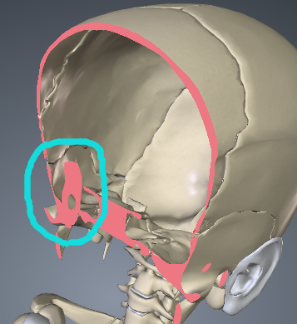
But what geometry are we going to use for the drawing? We need to use an actual geometry to draw the capping, and that geomtry should perfectly fit into the disclosure formed by all clipping planes. Drawing some random geometry cannot give us a visually correct result.
This is kind of a limitation. For only the axis-aligned clipping planes can we used a box to fit in. It needs extra work to make arbitrary plane working well.
We also use gl.stencilFunc to set the stencil test functions and only let the fragments where stencil value equals 1 to pass the stencil test and be drawn.
Improvement
The new method can create a much better clipping cap effect
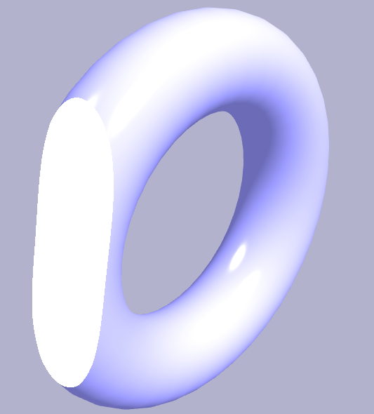
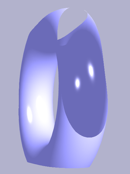
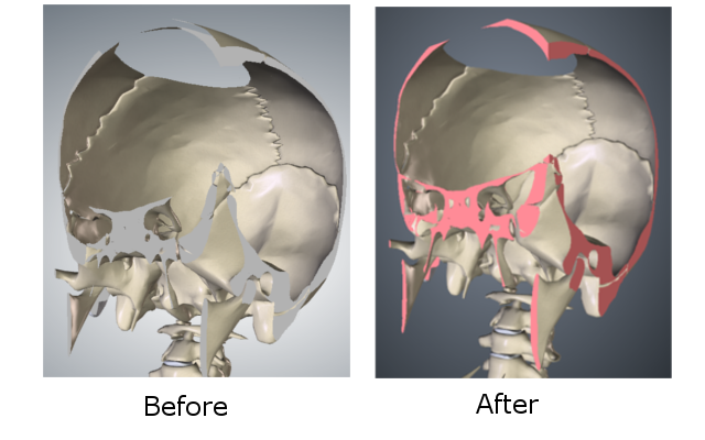
- Multiple clipping planes won’t break the illusion any more, as shown in the image below.
- We can now apply common shading techniques to the caps. Cuz now they are actual geometry planes.
- When WebGL 2 came out, we can even apply 3D texture to the clipping caps so the cross section for different part can have their own color and texture, which is super cool!
- I’m working on a 3D texture clipping cap demo in this Github Repo: clipping-with-caps
There are also limitations:
- We use 3 pass to achieve such a feature! This can impact the performance when we have a lot of draw calls.
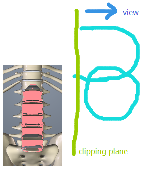
- This method still cannot work very well with arbitrary clipping planes unless we can create a geometry perfectly fit into the disclosure formed by all clipping planes in real time. See this SceneJS example to see what is the problem.